Biomimetic Elephant Seal Robot |
february 2009 - march 2009 |
objective: design and build a robot that can imitate the movements of a baby elephant seal as it climbs up a sandy ramp |
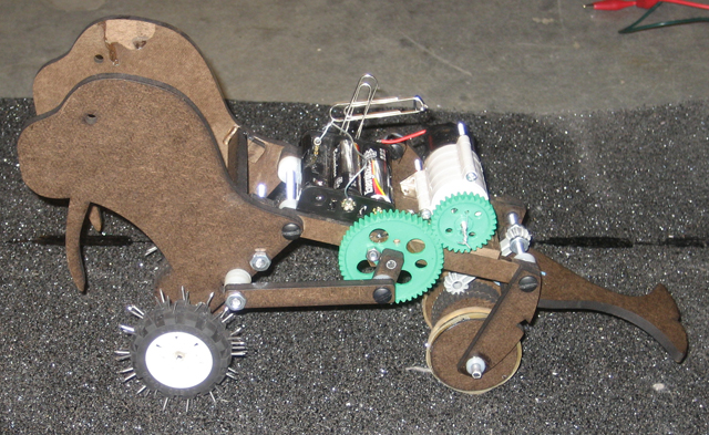
In February of 2009, our team “I am the Walrus” successfully recreated the galumphing motion of an Elephant Seal that could authentically crawl up a sandy beach for Lancaster Burton, Project Manager of ROSES. After thorough brainstorming and prototyping, we built our final design with two asynchronous four-bar masonite linkages that were 180 degrees out of phase to create a natural galumphing motion (Figure 1). One set of four-bar linkages controlled the head and another set controlled the tail, allowing the body to expand and contract much like an Elephant Seal. A Tamiya gearbox motor with a gear ratio of 167:1 powered by two AA batteries controlled the linkages.
|
 |
We used free-body-diagrams and torque analysis to spec out a motor for the task. We then refined Eggman’s stride by using Matlab in conjunction with physical prototyping. Solidworks also proved to be a useful tool in the iterative design process. It allowed us to change parts in our virtual assembly and address any interferences or instabilities before cutting new pieces of masonite. Our final design produced torque that was more than adequate to climb up the hill. In the final performance, Eggman smoothly galumphed his way up the sandy beach in 18 seconds. |
| Design development |
Overall structure |
|
Over a series of iterations, we developed our robot’s technical and aesthetic qualities. The following explanation highlights the development of several features. |
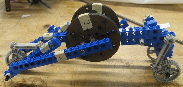 Figure 2: Lego prototype with two ratcheting wheels and 2 four-bar linkages Figure 2: Lego prototype with two ratcheting wheels and 2 four-bar linkages |
| After doing some research on Elephant Seals, we discovered that the body muscles, as opposed to fins, actually drive the galumphing motion. Our early prototypes had featured a simple design powered by two four-bar-linkage fins in the front that lifted the seal and dragged the body forward with a passive camshaft in the rear. We later refocused our efforts on creating a full body motion with a Lego prototype in which the flippers, head, and fins all played an integral roll—scrunching and extending in a caterpillar-like fashion (Figure 2). Although this design (with four bar linkages in both the front and rear) proved harder to balance and synchronize, it created a more unique biomimetic galumphing motion (Figures 3 and 4). |
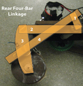 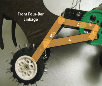 Figure 3: Rear four-bar linkage; Figure 4: Front four-bar linkage Figure 3: Rear four-bar linkage; Figure 4: Front four-bar linkage |
| Wheels |
Another key feature of our structure is the ratcheting wheels (Figure 5). We added ratcheting wheels to both the front and the rear to prevent the seal from surrendering any ground already covered. By using Lego pieces and lasercamming our own wheels, we had the freedom to decide their size and ensure that the ratchets would engage with the Lego pawls with accuracy. We used a rubber band to add a medium force between the pawl and ratchet, keeping it engaged with the teeth at all times. |
|
Although the ratcheting mechanism worked well, the friction between the wheels and the surface was not always large enough and the wheels sometimes slipped. We increased friction by adding rubber bands around the rear wheels, but still saw the front wheels slipping. Although we tried putting rubber bands in the front as well, we eventually transitioned to rubber Lego wheels for more consistent gripping. Finally, we found that poking nails through the rubber Lego front wheels resulted in the correct amount of grip and eliminated slippage on all wheels (Figure 6). |
| Although our seal design was compact and gripped well, it still occasionally flipped over as it galumphed up the sandy shore due to its high center of mass. As a result, we decided to spread out the two front nail-covered wheels to ensure stability. |
| Motor mounting |
A series of iterations were focused on motor mounting as we worked to find the correct location for the motor without sacrificing stability. By moving the gear to the outside of the main support beams, we were able to center the motor in the middle of our seal (Figure 7). |
However, placing the motor on top elevated the center of mass. Fortunately, this did not present an issue because we had already widened the wheels to broaden the seal and increase stability. In future iterations, we would attach the motor on the underside of our seal for a more elegant design. To control our motor, we fashioned a flexible switch from paper clips, which allowed us to easily turn our robot on and off (Figure 8). |
|
| Connections |
Another series of changes focused on the alignment of our seal. After we discovered Eggman's tendency to veer to the left, we realized he needed a more rigid frame. Since one linkage was driving the front left and another linkage was driving the rear right, the design is not symmetrical about its central axis. This coupled with the fact that the rotation of the two linkages was 180 degrees out of phase resulted in a lot of wobble and instability in the design. Therefore, we took a lot of time in order to minimize the degrees of freedom in the joints. We added support beams between the linkages and tightened them so that the frame would be less wobbly and also added a second support beam in the rear. To further stabilize the structure, we glued all the washers to the linkages (Figure 9). |
| Analysis |
We used a free body diagram analysis (Figure 10) to select an appropriate motor and gear ratio. In order to size our motor to the most conservative prediction, we assumed the worst-case conditions. We assumed that in the absolute worst case, the Eggman would have to lift himself perpendicular from a flat surface counteracting 100% of the gravity force. In addition, he would have to pull his weight forward overcoming all of static friction. Although static friction would never be overcome in actual operation (Eggman locomotes via rolling not sliding), we used static friction so that our calculations represented the highest possible forces in the x-direction. In actual operating conditions the forces Eggman would have to exert to counteract gravity would be smaller because of the 10 degree slope. Using these assumptions, we calculated that the highest required torque would be 0.416 Nm (see Appendix A for detailed calculations). We knew if Eggman was designed to withstand these torques, he would have no problem in real operation since he never actually needs to lift his entire weight - he simply extends, then pulls himself forward via wheels. |
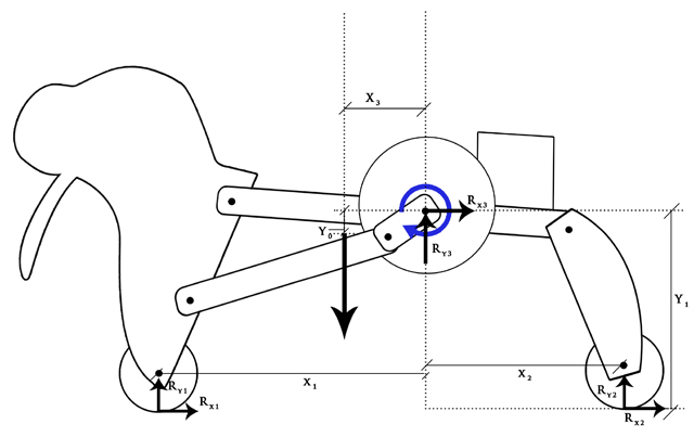 Figure 10: Free body diagram Figure 10: Free body diagram |
For our final design, we bought a Tamiya Planetary Gearbox Set so that we would have the flexibility to change the gear ratio if necessary. We decided to use the Tamiya gear reduction of 100:1 and add an extra gear reduction outside the motor of 5:3, giving an overall gear reduction of 167:1. This resulted in an adequate speed of locomotion up the slope in under thirty seconds. At this gear ratio, we measured an output torque of 0.84 Nm at stall conditions. Although this is above our worst-case design requirement, we decided it would be beneficial to have a safety factor of available torque over the worst-case scenario in order to account for frictional losses in the design. |
|
|
| Having settled on this gear ratio, we decided to model the linkage motion. We used Matlab to analyze whether our idea for out-of-phase linkages would trace a reasonable path and create a steady velocity without any huge velocity spikes. In Figure 11, we traced the front and rear linkages and tweaked the lengths until the paths that they swept were large enough to ensure that the Eggman would travel up the sandy slope in under thirty seconds. We plotted the velocity of the output of the linkage as a function of the time in one cycle (Figure 12). We were satisfied with the resulting smooth velocity curves, which would ensure an easy galumphing motion without any velocity spikes (and therefore no abrupt force peaks). |
| Solidworks |
We used Solidworks to visualize and refine our movement. Once we had a working Lego prototype, we translated our model into Solidworks. In Solidworks, we found that these Lego links were in fact unstable due to unforeseen collisions with other pieces (Figure 13). By simulating the movement of each design iteration, we were able to experiment with different linkage dimensions so that we could find the smooth galumphing motion that we were looking for in a stable design (Figure 14). |
Not only did Solidworks aid with the overall movement, but also with seal features like the fins. During this process, we were able to move the assembly to ensure that our fins did not collide with any other parts. |
|
|
Results and Final Testing |
| Interestingly, we found that the maximum required torque occurred 180 degrees out of phase compared to what we expected. In the preliminary analysis, we predicted the highest torque requirement would occur when the seal was in the fully extended position (Figure 15 on following page). However, through measuring the current in the motor while the seal moved up the hill, we found that the highest torque requirement actually occurred when the seal was in the compressed, or scrunched up, position (Figure 16 on following page). In this position, we measured that the current in the motor was 1.55 A, corresponding to a maximum torque requirement of .27 Nm. The torque is maximized in the closed position for several reasons. The first is because this is the point at which the front end is coming to the end of its pulling motion in which it drags the weight of the seal up the slope. The current drawn by the motor continuously increases through this pulling motion as the motor continuously bogs down. The second reason is due to the placement of the tail. When the seal is in its most compressed position, the rear end is swinging forward before it starts its pushing movement. Before it gets to the position where it starts to push, the tail briefly hits the ground and drags, lifting the rear wheel off the ground. The rear end is no longer rolling up the incline; rather, it is sliding on the tail. The result is that more torque is required from the motor at this point in the cycle since much more friction is involved with sliding than rolling. We decided to retain the position of the tail even though it resulted in increased friction because the tail planted solidly on the slope when the rear end was pushing back, helping prevent slippage down the slope. In addition, the movement was deemed more seal-like with the tail briefly striking the ground. This galumphing movement was the most important design criteria, providing lots of incentive to accept a slight increase in friction and torque for the sake of realistic movement. |
|
| Testing validated our preliminary torque analysis derived via our free body diagram seen in Figure 10. Based on worst-case scenario assumptions described earlier, the highest required torque spike was predicted to be .416 Nm. In actual testing, we found that the highest required torque was about .27 Nm. This was to be expected as operating conditions were much less demanding than our preliminary analysis using worst case assumptions described earlier. |
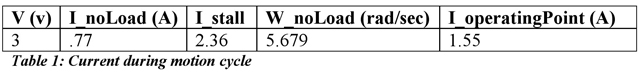 |
The operating point seen in Table 1 is the maximum current required by the seal in its motion cycle, corresponding to the point of maximum torque requirement. Taking the 1.55 A measurement and running through calculations based on InoLoad, Istall, and ωnoLoad, we were able to conclude that the highest torque required to power the seal was .27 Nm. |
Table 2 highlights how the addition of the tail impacted the performance of the seal. Based on the current of 1.2 A, we realized our power train was operating a little to the left of the efficiency peak of 18.2% (Figure 1 Appendix B). Both with and without the tail, the operating current was close to the peak efficiency, so we decided to keep the more authentic galumphing motion despite the extra power consumption. |
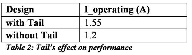 |
Adding the tail supported some of the weight, increasing the normal force and therefore the friction force at the tail-ground interface. On one hand this was bad because the required output of the motor increased. On the other hand, this could be a beneficial side effect because the tail provided more grip on the terrain and decreased slippage. This was the dominant reason in keeping the tail in this location. |
| In order to determine the overall efficiency and losses in the system, we ran a comparison between no-load conditions in air and actual operating conditions on the sandy slope. The no-load conditions in air represented the internal frictional losses to rubbing in the linkages and misalignment. Taking the average v and i as the seal climbed the slope, we were able to identify the actual power consumed. Subtracting the frictional no-load power consumption from the actual power, we were able to identify the ideal power consumption of the seal. Using the following equation, we calculated the efficiency: |
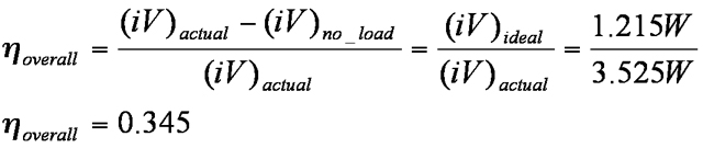 |
| Our seal design was successful despite the risks we took by implementing an unusual design. The strength of our design lay in our lightweight, robust, and low power consumption. The wheels contacted the surface without slipping and the body galumphed realistically with asynchronous four bar linkages in the front and rear. The weaknesses of our design stemmed from its asymmetry, which led to misalignment and unbalanced forces, and the high center of gravity, which led to instability. If given the opportunity for future development, we would reposition the motor, widen the body, and develop a more biomimetic mechanism that grips to the sandy shore without wheels or nails. With these changes we believe Eggman could move confidently among the bulls and their harems at Año Nuevo providing project ROSES with valuable insights. |
| Appendix A: Free Body Diagram Analysis |
| Appendix B: Motor Analysis |
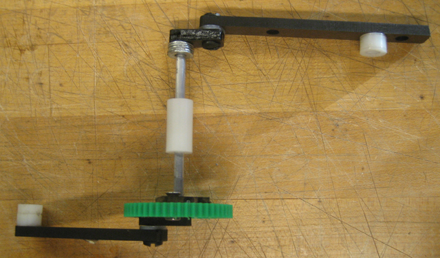 Figure 1: 180 Degrees out of phase
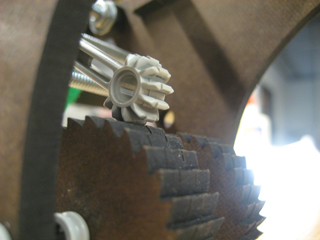
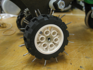 Figure 5: Ratcheting wheel; Figure 6: Nails in the rubber added traction
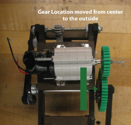
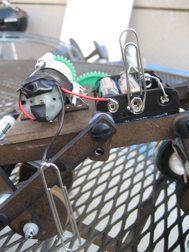
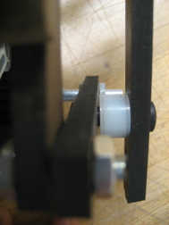 Figure 7: Moving gear to the outside; Figure 8: Paperclip switch; Figure 9: Rear linkage connection
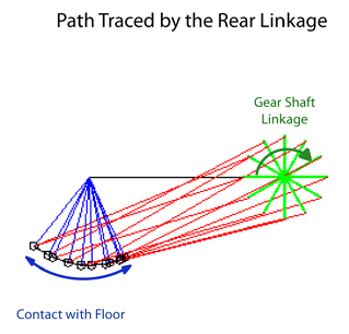
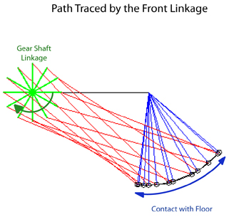 Figure 11: Paths traced by rear (left) and front (right) linkages
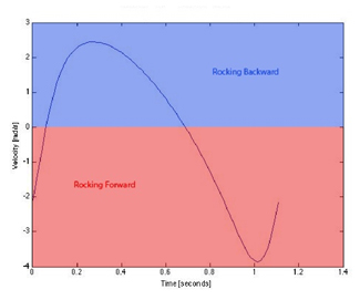 Figure 12: Velocity vs. time for rear (left) and front (right) four bar linkages
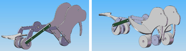 Figure 13: Assembly with collision piece in green (left) revised assembly (right)
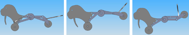 Figure 14: One Solidworks simulation where we saw an unstable configuration.
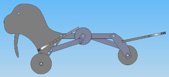
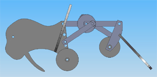 Figure 15: Seal in extended position; Figure 16: Seal in compressed position