Mechanical
|
||
Team 15: "Do It"
|
||
Driving Base |
||
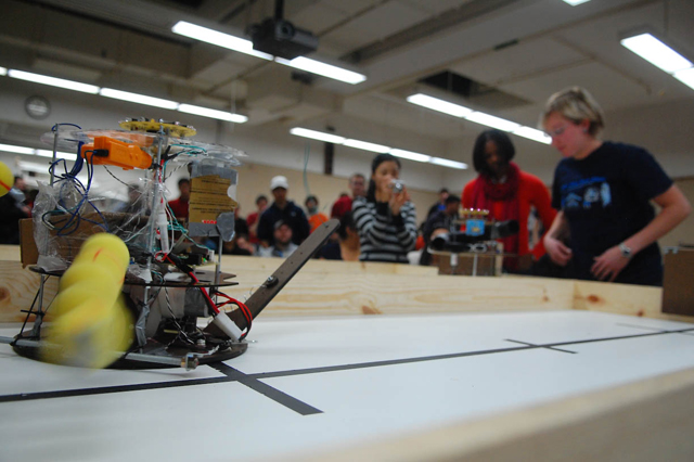
Our drivebase was made out of Masonite. We decided to use Masonite for its high strength and the ability to drill through it. We chose to go with the circular base design as opposed to the rounded square. We figured that if we needed to have a straight edge we could add some material more easily than if we chose a rounded square and needed a circular edge. The drivebase contained slots for the wheels and mounting points for the motors and the large screw shafts that would hold the upper platforms of our robot. We set the distance between two wheels relatively short to make the robot faster when spinning. The base of our robot was designed low enough so that under which no nerf ball can be stuck. That initially brought us a problem that there was too much friction caused by those screws under the base unnecessarily touching the ground. We first tried Teflon tape on those screws but that didn't’ work very well. Later we grinded down those screws using a dremel, which gave our robot a better performance. |
||
 |
||
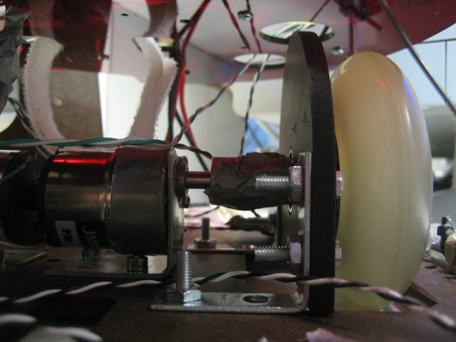
| Motor and Wheel Mount | ||
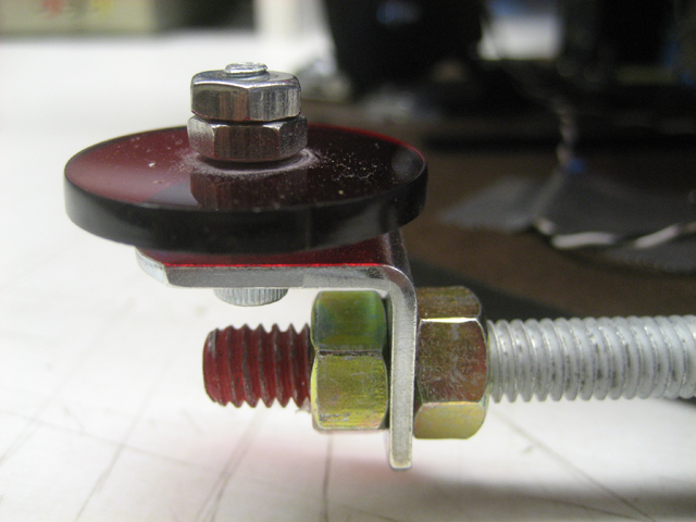
During our meeting with out coach, the topic of how the wheels will be mounted with the motor posed particular interest. It was mentioned that mounting the wheels directly to the motor and running them directly to the ground was a bad idea and that the motors would give out in a matter of weeks, just in time for the competition. The reason for this is that the normal force of the ground pushing against the wheels would transfer to the motor, and that the motors were designed to take rotational and axial loads, but not normal loads. This type of normal loading would destroy the motor. We decided to attach the motor to a d-shaft using a spider coupler system. The shaft would then be attached using a bearing to a rigid housing structure. This way the bearing and structure would take all the normal loading and the motor would not. The wheels, which were in fact 83mm roller blade wheels, were attached to the d-shaft using bearings. Since an appropriate d-shaft could not be purchased that matched the dimensions of our motor shaft, we manufactured our own shaft to meet our size specifications. The wheel mounts were also made out of Masonite and secured to the drivebase using c-joints screwed in place. The driving system connection is shown as follow: Motor -> Spider Coupler -> Shaft -> Bearing + Strut -> Wheel Insert -> Wheel |
||
 |
||
Analysis |
||
| Motor Vince 6 V | ||
| Motor Vince 9 V | ||
| Motor Vince Graphs | ||
| Motor Ben 6 V | ||
| Motor Ben 9 V | ||
| Motor Ben Graphs | ||
| Circuit Platform | ||
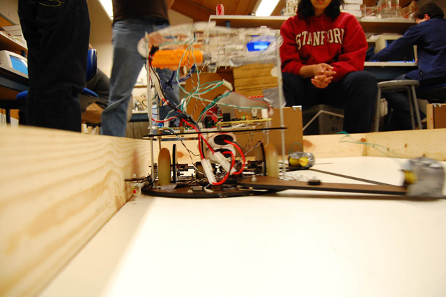
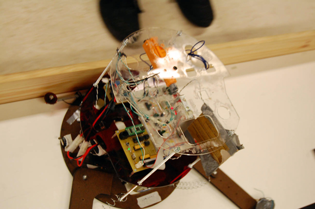
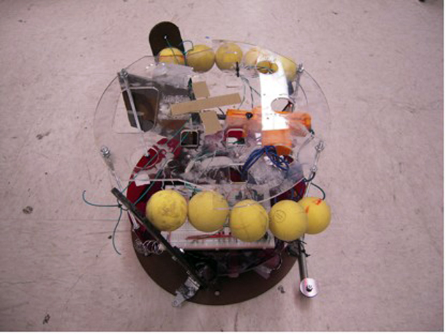
Above the drivebase rests the circuit platform. This platform houses the main circuitry of our robot including the C32 microcomputer, the breadboard, and the motor-board. The platform was manufactured out of red acrylic. This was because it was lighter than Masonite and we did not want the robot to be top heavy. For competition a shield made of cardboard would be added to the circuits to protect them from flying Nerf balls. Additionally a sheet of plastic cellophane wrap provided additional protection from the flying projectiles. Lastly the platform served as the mounting point for the batteries. Whereas most teams had the batteries mounted on a base we had our batteries suspended from the circuit platform over the drivebase attached with Velcro. The decision was based on the fact that there was no room on the drivebase to house both batteries. We did not particularly like the positioning of the batteries because they were susceptible to heavy vibrations caused by the collision of the robot to the arena walls. Nevertheless, with heavy reinforcement, the battery remained in place. |
||
Wall Guide |
||
During testing of the robot it was found that the robot had difficulty maintaining a straight line. We decided that the round shape of the robot did not aid it in following the wall and that it had a tendency to deviate its angle as it followed the wall. We added a rod to the wall following side of the robot with hopes that the straightness of the rod would help the robot maintain a straight motion. However, adding the rod did not solve the problem. In fact it created a new problem: friction. The robot was still moving at an angle. This caused one side of the rod to rub against the wall excessively, generating a lot of friction, and reducing the overall speed of the robot. In order to counter the friction problem we added rollers to the ends of the rod. The rollers were made out of acrylic and were allowed to free spin, which significantly reduced the friction between the robot and side walls. |
||
 |
||
 |
||
 |
||
Arms, Bumpers, and Arm Release |
||
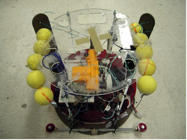
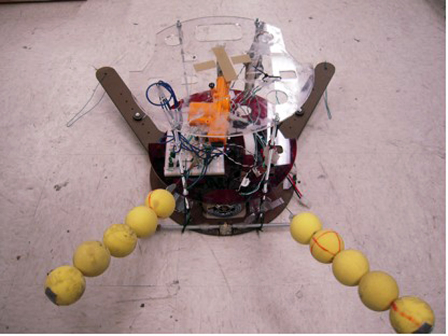
Because the size limitation required our robot to be less than 12 inches, in order to hit the bumpers while following the wall we needed some kind of extension that protrudes from the robot. The arms that we designed were manufactured out of Masonite. The arms are shaped like an “L”. They are attached to the drivebase at the intersection of the two lengths by a set of screws and nuts. When the arms hit the bumpers the arms pivot at the joint hitting the leaf switches on the robot indicating contact has been made. Large springs attach from a central point on the arms to the robot base in order to provide a restoring force after contact with the bumpers. The arms had to be contained in the robot prior to the start of the competition and then extended when the competition began. Our arms were attached to a set of hinges at the base. These hinges permitted the arms to be raised and tucked into the robot. While in this state the robot does not exceed the size limitations. The arms are held up by wire connected to a door lock motor. After the robot has found its orientation the motor retracts, the wire connected to the motor is released and the arms then drop freely into position. With this arm system, not only the robot had a greater length after triggering so as it could travel less distance to hit the wall, but also the bumper sensing system was easier and more reliable to trigger. |
||
 |
||
 |
||
 |
||
 |
||
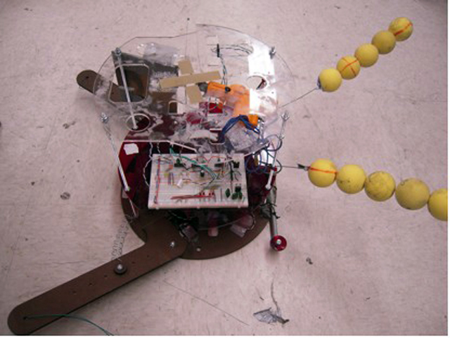
| Last Minute Changes | ||
We realized that other robots employed the same strategy for getting points, but these robots were faster than ours. We would not win by hitting the bumpers alone. We did not have the time to construct a viable shooting mechanism, but we needed a method of scoring more points using the Nerf balls. At the last minute we added two music wire antennae with balls strung through them. The antennae would be tucked in underneath the arms, when the arms are released so are the antennae. These antennae would extend over the middle wall and contact the opposing robot when it passes by. This would potentially allow us to get extra points and defeat the opponent. |
||
Tong Zhang | Agustin Ramirez | Nina Joshi
|
||
last updated 3.12.09 |
||