| Bill of Materials |
Purchases |
|
Supplier |
Description |
Amount paid ($) |
|
SPDL |
74HC595 (2) |
1.60 |
|
SPDL |
Wire, molex connectors, resistors, etc. |
5 |
|
SPDL |
Wire, solder |
5 |
|
Ace Hardware |
Hardware, hinges |
31.41 |
|
RadioShack |
Lamps, sockets, diodes |
12.60 |
|
SPDL |
Wire, molex connectors, resistors, etc. |
2 |
|
SPDL |
Components for Servo Driver Board |
15 |
|
SPDL |
Components for Voltage Regs |
5 |
|
Home Depot |
Super Glue |
3 |
|
SPDL |
Components for Photo Interrupter Circuit |
5 |
|
Savers |
Steering wheel unit |
6 |
|
Home Depot |
4 x 8 Ply Sheet |
10 |
|
ThinkGeek |
RC Mini Cooper |
28.50 |
|
|
|
|
|
|
|
|
|
|
|
|
Other Components we had previously or found |
|
|
Suggested Value ($) |
Description |
|
|
2 |
Fasteners, 4-40 |
0 |
|
5 |
Fasteners, 6-32 |
0 |
|
40 |
Acrylic |
0 |
|
30 |
Aluminum |
0 |
|
|
Servos (3 at 3.50 each) |
10.50 |
|
5 |
LEDs |
0 |
|
|
Black matt board |
0 |
|
|
Masonite board (where we put our circuits) |
C. O. F. |
|
|
Components for C32 Interface board |
C. O. F. |
|
|
Components for motor driver board |
C. O. F. |
|
|
|
|
|
|
|
|
|
|
TOTAL: |
140.61 |
|
| |
| The Driving Scene |
In The Italian Job movie, the expert team of thieves must figure out how to transport stolen gold through the crowded streets Las Angeles. Our expert team had to design and build the streets themselves...and the buildings too!
|
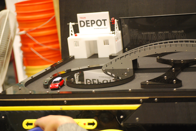 |
Roads |
We designed our driving scene to be fun yet challenging, combining deceptively simple looking road elements with sweet turns and even a bridge. Experienced, talented, and lucky drivers could sometime complete the drive from the train depot to the bank less than five seconds, while other drivers found it difficult to complete the task in the forty-five second time limit. |
Our 1:56 scale Remote Control Mini Cooper needed a 1:56 scale environment to drive around in. Restricted to 24” by 36” for the absolute board dimensions, we were faced with a substantial challenge to make the board fun, fast, and challenging. We measured the turning radius of the RC Mini Cooper (6.5 inches) and designed all the road curves to match that radius, to better maintain the car’s speed through the course. |
| There is a bridge in the center of our board to spice things up, accessible by onramps which split off the main road at the front of the board. The center of this main road has a small bump in one side which will guide the car onto the bridge onramp unless the driver takes corrective action. This prevents drivers from simply following the edge of the main road around the whole board. For the same reasons, we offset the entrances to the buildings so that the car wouldn’t easily enter, guided by the road edge. |
 |
| There is a circle in the road in the center of the board with and entrance on either side. To the anxious thief, this might look like a fast shortcut, only to find themselves completing a time consuming eighteen-point turn to escape the “circle of death.” |
| Roadway Assembly |
| The driving scene is constructed from Acrylic Plastic, Masonite, Matboard, and MDF. The base rectangle was cut from three-quarter inch thick MDF, a super dense artificial wood. On this rectangle is placed black Matboard, which forms the roadway surface. Two layers of, laser-cut, one-quarter inch thick Masonite are topped with one-sixteenth black Acrylic and bolted into place on the base rectangle. The roadway was removable from the base of the flicker to allow access to the electronics. |
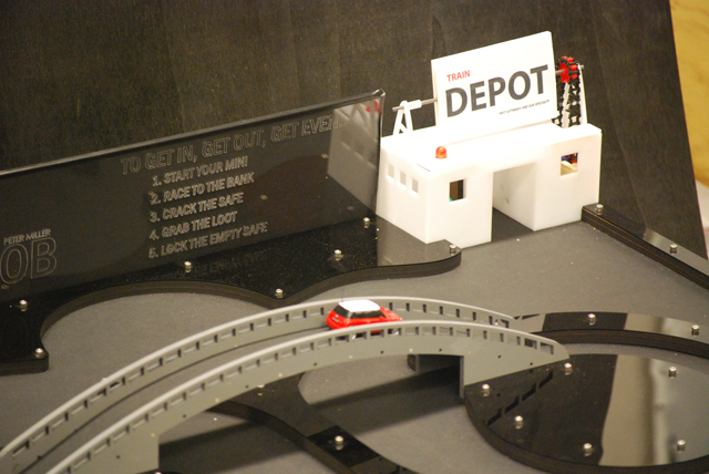
| Buildings |
| The bank and train station are the two buildings included in our driving scene. They are identical in appearance and assembly. This was done on purpose, because either building can be the ‘bank’ or ‘train depot’, depending on the position of a double sided rotating sign atop them. This way, we can always have the RC Mini Cooper racing towards the bank (which, in addition to saying “Bank” above it in big letters, also has a flashing LED). The buildings have a small parking space build into them which detects the presence or absence of the model Mini Cooper. |
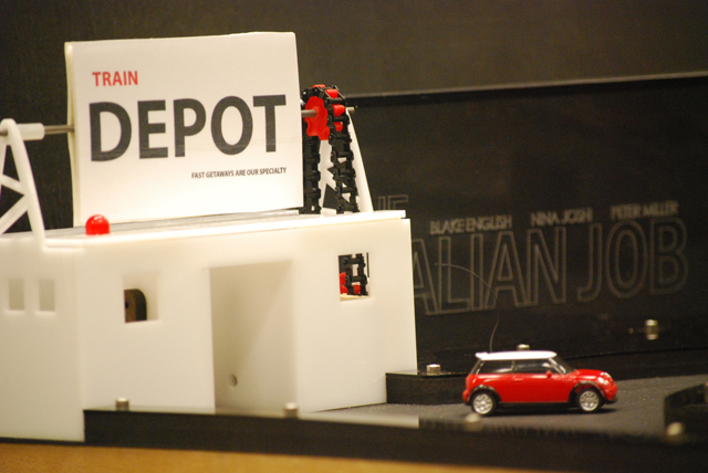 |
| Buildings Assembly |
| The structure of the buildings is one-eight inch thick white Acrylic that was cemented together with Acrylic cement. Across the parking space is aimed an IR LED and IR Phototransistor pair which detect the presence of an object in the parking space. The buildings each have a rotating sign which says “Bank” on one side and “Depot” on the other side. A RC hobby servo is connected to a chain drive with a 1:2 gear ratio to the sign, which pivots on a one-eight inch diameter steel shaft. The RC hobby servo is attached to its mount with screws and the mount is attached to the buildings’ Acrylic sides with epoxy. There is a large LED on the roof of each building to help indicate to the driver which building to drive to. |
| |
| |
| The Safe |
| Final design |
| First Parts: |
| Because so little time was given to complete the project, we decided to forgo prototyping of most safe assemblies and instead base our decisions on what information was garnered from the CAD models. However, to ensure a proper sense of scale and a proper feel for the user, the safe dial and lock lever were machined without the use of engineering drawings or even sketches. First, a piece of 5”-diameter aluminum round stock was turned down to size on a lathe until a proper feel was achieved; the lock lever was then machined to the same scale as the dial. |
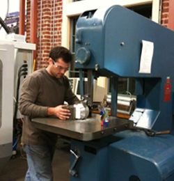 Parting the safe dial from round stock. Parting the safe dial from round stock. |
| Some details of the safe dial are worth mentioning now: The dial knob was knurled with a large knurling tool to give the proper touch-feel to the dial, and numerals were stamped by hand into the dial face with a set of dies after the part was sanded and polished. The lock lever arm was pressed into its base at a thirty degree angle to provide clearance for the user’s hand. |
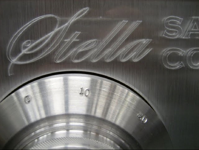 Numerals stamped with a die set; dial knob is knurled. Numerals stamped with a die set; dial knob is knurled. |
 |
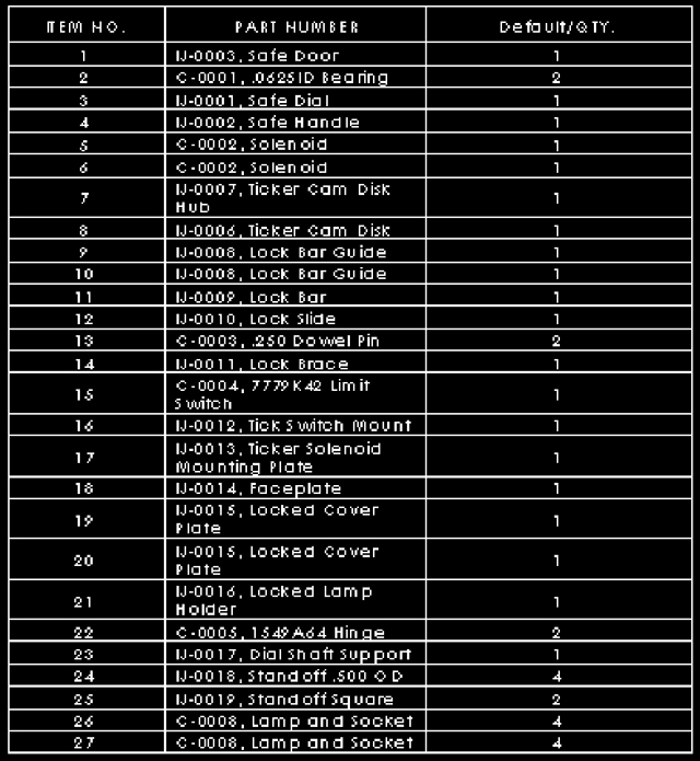 Bill of Materials, safe door Bill of Materials, safe door |
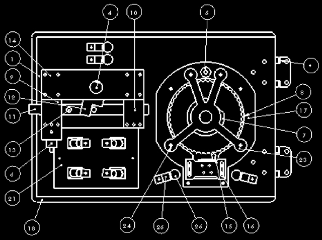
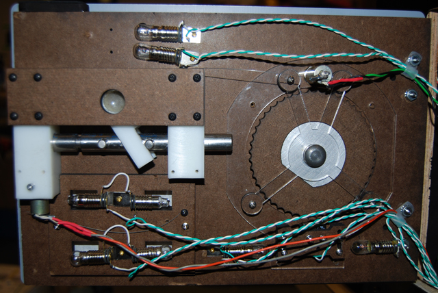
| The design of the dial and switch assembly was the first assignment to tackle: |
- Note that during the machining process, a pneumatic ram was used to press a 5/8” steel dowel pin into the back side of the dial (3) where it would serve as its axle. A 5/8”-ID bronze flanged bearing (2) was sourced to support the safe dial; it is depicted in the model.
- An aluminum hub (7) was then designed to support a cam wheel (8). This wheel ,when cut out of .225” Masonite sheet on an NC laser cutter, would have 48 cam lobes offering ~.085” of lift. By this time we had sourced a small limit switch that required ~.070” of lift to operate, and we were convinced the cam wheel would interface well with the bearing-end of the limit switch (15). However, we designed an adjustable limit switch mount (16) that would allow us room to set the interference between the limit switch and cam wheel; thus we could set the switch for proper on-to-off operation with rotation of the dial. Finally, this hub and cam wheel would be pressed onto the dial axle and locked with a set screw.
- A cam wheel guard (17) was constructed to protect the fragile Masonite cams; this piece was also designed as a mount for a small solenoid (5). The axis of this solenoid would run normal to the rear face of the dial, and when fire, the solenoid ram would strike the dial, resulting in a small vibration and a high-pitched ring that would indicate to the place that he reached the target ticks for this stage of the safe cracking operation. The cam guard was to be made out of acrylic due to its strength over Masonite.Finally, a cross-member (23) was erected to support the far side of the dial axle shaft.
- Finally, a cross-member (23) was erected to support the far side of the dial axle shaft.
|
 Safe dial assembly, transparent view Safe dial assembly, transparent view
|
| With the dial complete, the locking mechanism was next on the list: |
- Again, the safe door was to convey a sense of robustness, so a bolt (11) was fashioned out of ½”-diameter 304 stainless round stock. It featured two holes reamed to .249” to accept the press fit of two ¼” dowel pins (13); these pins act as end stops and engagement pins for the bolt. The 1/8” groove was also made in the bolt to accept the ram of a small solenoid (6); this would allow the bolt, and thus the door, to be locked when the solenoid is engaged.
- The guides (9, 10) for the bolt were then designed to be made out of a machinable plastic. Tightly-toleranced bolt holes would prevent slop in the system, and multiple tapped holes for mounting to the safe door (1) on one side and a brace (14) on the other would maintain rigidity. Note that the bolt guides are not of the same length: the longer of the two (9) was designed to house the lock solenoid (6) that engages the bolt; a set screw holds it in place.
- The lock lever (4) again pivots on a 5/8” dowel pin and bronze flanged bushing.
- A finger block (12) is mounted to the lock lever on the inside of the safe door. When the lever is rotated, the finger block retracts the bolt to unlock the safe. This piece was also designed to be cut from a block of plastic due to its inherent flex and spring rate. The circular bolt was of known diameter (.500”) and the slot in the finger bolt was designed to be ~ .030” smaller than the bolt. As a result, when the fingers rested on the bolt, the natural state of the locking mechanism was fully locked or fully unlocked. To reiterate, the plastic finger block was designed to squeeze the steel bolt; the fingers would deflect and move the lock lever into one of two positions, fully locked or fully unlocked. This design would allow us to construct a locking mechanism that uses no springs to maintain the position of the bolt.
|
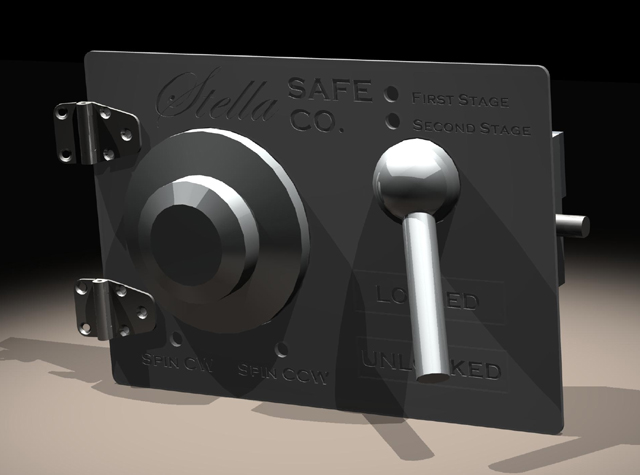
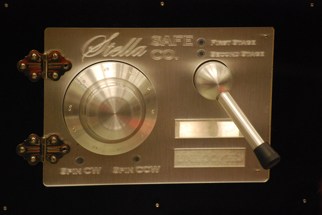
Finally, the exterior appearance: |
- The acrylic sheet for the safe fascia was sourced before the safe design was completed; it was clear with an aluminum-like veneer on one side. The fascia was designed to be etched with a laser cutter, then the aluminum veneer at indicator locations would be subsequently machined away.
- Locked and unlocked plates would be set in place, flush with the safe fascia, over paired incandescent lamps.
|
 Safe door assembly Safe door assembly
|
| Implementation |
 The completed safe The completed safe
|
All According to Plan: |
Generally speaking, the safe went together as designed. Ten individual and unique parts were machined; the rest were cut with a laser cutter. |
Further Adjustments: |
| In terms of the mechanical system, the major change to design between the CAD model and final assembly was the addition of two return springs to reset the solenoids when power was removed from these components. |
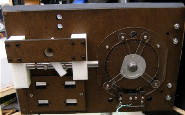 The safe door before wiring is installed The safe door before wiring is installed
|
Installation: |
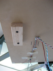
| The safe door was installed in the main box assembly by mounting it on a pair of small steel hinges. A piece of faux granite was placed in the bottom of the safe module it was then lined in heavy black matte board. Another small limit switch was placed in the upper right corner of the safe door opening; the switch is used to monitor the state of the safe door. A formed wood piece was placed in line with the safe bolt to guide it into place when locking the safe door. Finally, a phototransistor was placed opposite an IR LED inside the safe; this allows the microcontroller to monitor if the safe has been entered. |
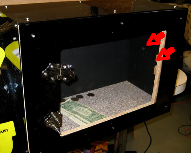 The phototransistor sensor and bolt guide inside the safe The phototransistor sensor and bolt guide inside the safe
|
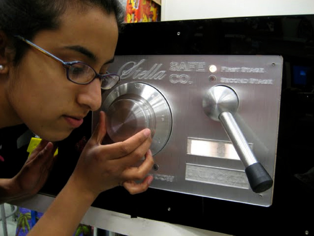 The safe in use The safe in use
|
 The safe door, complete with wiring The safe door, complete with wiring
|
| |
| Integration |
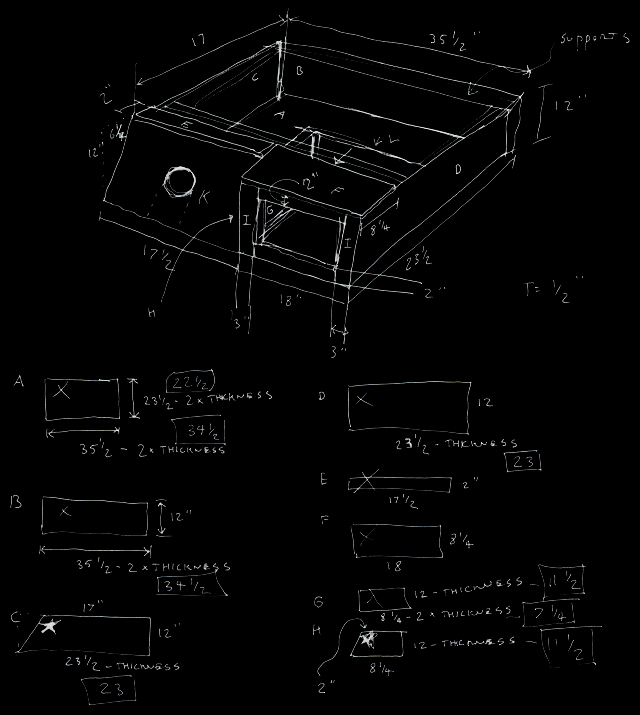
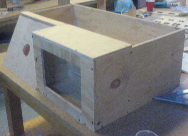
The Frame |
This plywood framed, Acrylic clad, behemoth of a box, contained the electrical systems of our flicker, and supported the driving scene, steering wheel and safe. The safe area was integrated into the plywood box, under the driving scene. |
 |
 |
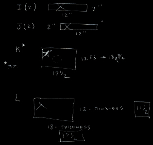
Frame dimensions |
 |
| The driving scene snapped securely into place with a tongue-and-grove design, and allowed us access to the flicker internals when removed. |
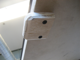 
Tongue-and-grove design used to integrate board with frame |
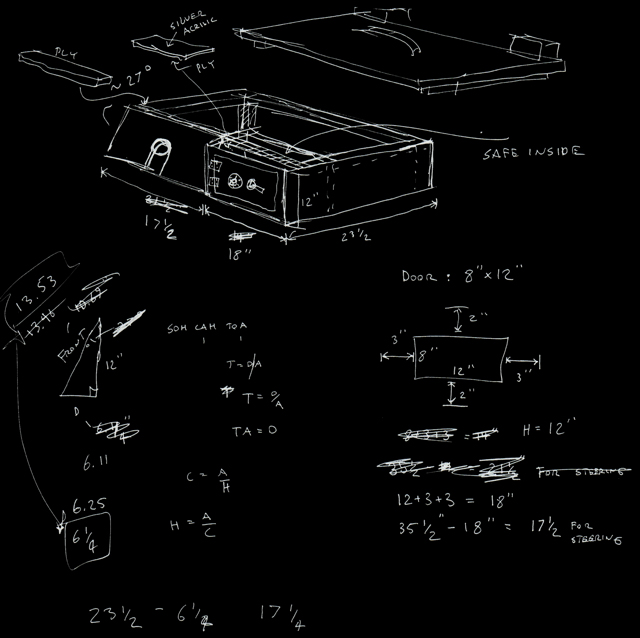
| The steering wheel, ignition switches, and gas gauge were mounted to the left sloped dashboard panel. |
| |
The Dashboard |
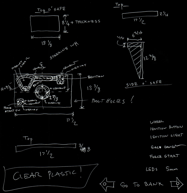 Dashboard paneling and frame dimensions Dashboard paneling and frame dimensions |
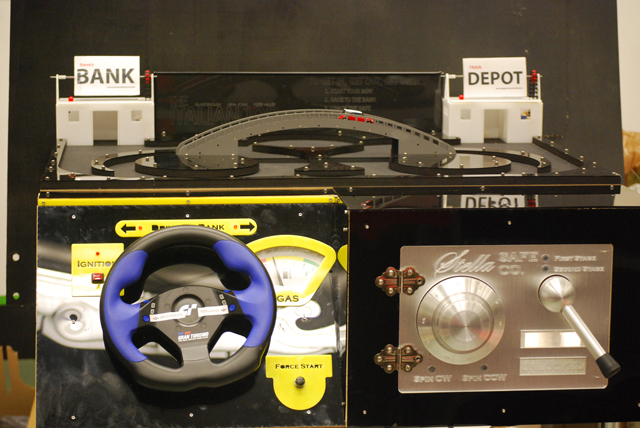 |
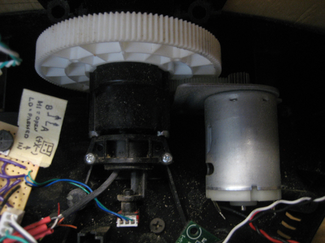
| Driving our mini is fun. There is an ignition switch that starts the car’s engine. We used a force-feedback steering wheel gaming control for steering and rigged up the system’s internal motor to provide engine-like vibrations through the steering wheel when the car ignition was turned on. |
 |
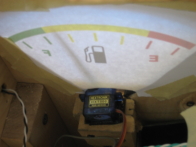
| The over-sized gas gauge indicated how much time remaining the player had, and a loud buzzer was triggered if they ran out of gas. |
 |
| Two buttons on the steering wheel controlled the mini’s forward and backward motion. A non-standard pair of indicator lights above the steering wheel indicate the direction to the bank, almost like a GPS! |